
HOMECALENDAR RESULTS LINKS RULES PHOTO ALBUM
BUILD A MINI
Last updated 15 October 2023
Mardave Mini Assassin Build Instructions
General notes
Screws into non-nyloc nuts or other threaded metal parts should be thread-locked
to ensure they do not come loose.
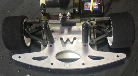
Front Suspension
Assemble as shown in the instructions; ensure that the front hub is the correct
way up, the plastic boss on the hub goes inside the spring. The kingpins now
come with a smooth coating so they don’t need to be polished, but you do need to
ensure that the hub moves freely on the kingpin.
When bolting to the chassis use a total of 4mm of spacers in the front lug, and
2mm of spacer in the rear. This should give you the correct ride height (3.5 to
4mm) with the tyres supplied. Adjusting the front ride height is done by
changing these spacers.
.
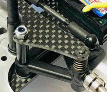
Rear Pod
Assemble as shown in the instructions. But note that the screw goes through the
other side, not as shown in the instructions.
When fitting the parts to the chassis, leave the centre rear pin loose until the
pod has been attached and ensure the pod moves freely on the pin, don’t forget
to snap the pod plate onto the ball stud, and only screw the spring retaining
nyloc nuts just on far enough for the thread to be through the nyloc section of
the nut, not 5mm further as in the instructions. This should give the correct
ride height with the tyres supplied in the kit. The rear ride height is set by
adjusting these nuts. Note the two rear bodyposts are not part of the kit.
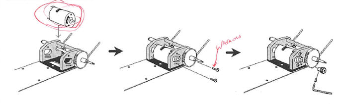
Rear Axle & Motor
Assemble as shown in the instructions. Note that a second gear is used on the
axle, not the spacer shown in the instructions. Solder the wires onto the motor
before fitting it to the pod, but note that the motor goes on the other side of
the pod to that shown in the instructions for normal rotation direction, or fit
it as shown but solder the wires on the opposite way around.
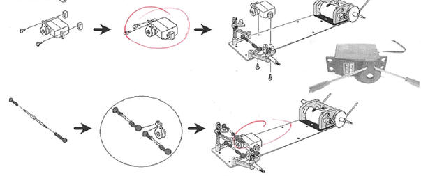
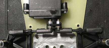
Steering Servo & Tie-Rods
The middle holes on the servo saver are used, and will need to be drilled out
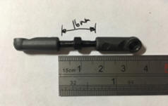
before fitting the black ball studs. The tie-rods have a right hand thread on
one end, and a left hand thread (anti-clockwise thread) on the other. The right
hand thread is indicated by the longer un-threaded portion. The opposite handed
threads allow for toe angle adjustment without removing them from the car. Screw
the ball cups on so roughly the same amount of thread is showing on each end,
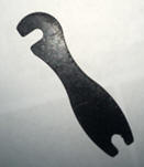
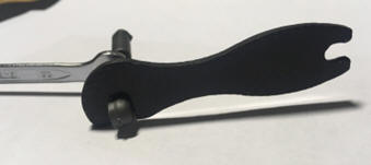
and there is approximately 16mm between the ends of the cups. As these are
Schumacher ball grippa cups a Schumacher spanner is helpful when screwing them
on.
Note that the servo in the instructions is shown the wrong way round. It is
important to have the output of the servo on the centre-line of the car. The
best way to achieve this is to use a ruler to put a pencil mark at the centre,
either side of the clearance hole in the chassis and then line up the servo by
eye. Before fitting the saver to the servo, make sure it is centred properly by
connecting all the electrics and powering on.
Bodyposts & bumper
Assemble the rear body post as shown in the instructions. Ensure that the rear
pod still moved freely, you may have to file the back of the posts to ensure
there is clearance.
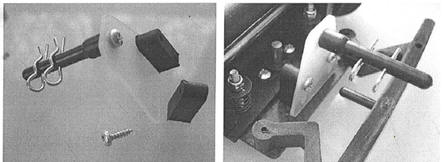
The front bodyposts hold the bumper onto the chassis. Note which holes to use to
give the best fit of the bumper with the kit Mini bodyshell.
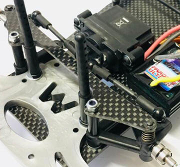
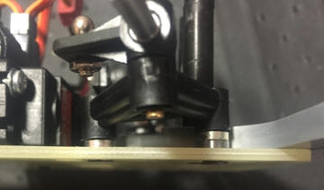
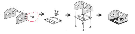
Battery holder
Assemble as shown below. Note which way round the GRP parts are fitted.
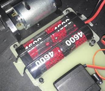
Electrics
Electrics placement is your choice, I would recommend fitting the ESC at the
side of the servo, & the receiver either on the chassis or on top of the servo.
Ensure that they do not foul any moving parts.
Wheels & Tyres
Rear wheels; The nuts should be tightened fully. Ensure that the wheel is fitted
correctly onto the drive from the gear.
Front wheels; one bearing on the inside of the wheel, the other on the outside.
Tighten the nut fully to seat the bearings then slacken it off until the wheel
spins very freely but does not move side to side.
Suspension Settings
Check the ride height front & rear is 3.5mm to 4mm, slightly higher at the rear.
As foam tyres wear, the ride height will need to be checked regularly and
adjustments made to the rear and spacers taken away at the front. Always have
2mm more spacers on the front screw than the rear. Schumacher do a set of
2mm,1mm, &0.5mm spacers, part number U3131.
Set the front toe to have the wheels parallel (zero toe), and the car running
straight.
It is also important to set the rear springs on both sides to avoid tweak. Even
though it’s simple to do, I’m not going to even try to explain the way this is
done using words; it’s something you will need to be shown. Ask one of the
experienced GT12 or LMP drivers to show you how it’s done.
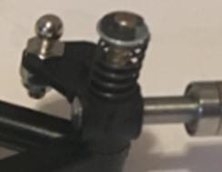
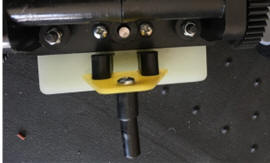
Optional Kingpin brace
This is fitted as shown below. The washers that fit between the spring and the
circlip on kingpins is not required.